
BMS JK-B2A8S20P-HC Setup Instructions
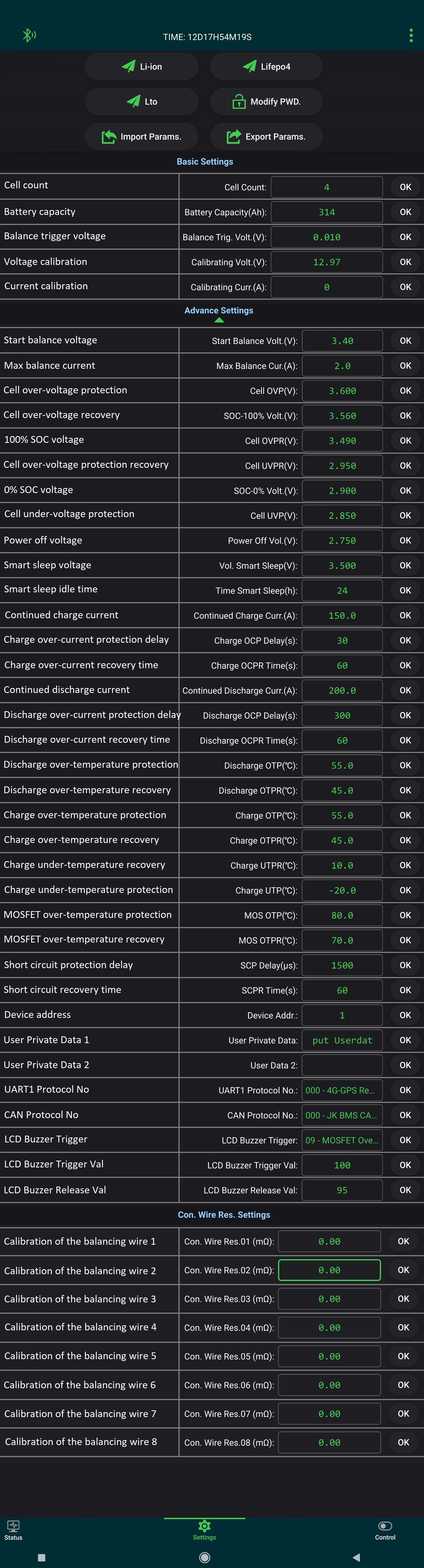
JK-BMS Configuration Guide (B2A8S20P)
This guide provides recommended settings for LiFePO4 batteries (4S/12V or 8S/24V systems). Please be cautious: incorrect parameters may lead to battery damage.
1. Basic Settings
| Parameter | Explanation & Recommendations |
|---|---|
| Cell Count | The number of physical cells in series. For 12V set to 4, for 24V set to 8. |
| Battery Capacity | The nominal capacity of your battery pack in Ah (e.g., 304Ah). |
| Balance Trig. Volt (V) | The voltage difference between cells that triggers balancing. Recommended: 0.005V – 0.01V. |
| Calibrating Volt/Curr | Used to calibrate BMS readings against a high-precision multimeter. Do not change unless you see a discrepancy. |
2. Advanced Voltage Settings
| Start Balance Volt (V) | The voltage level where balancing starts. For LiFePO4, 3.40V - 3.45V is optimal. |
| Max Balance Curr (A) | Active balancing current. Usually set between 0.6A and 2.0A depending on the model. |
| Cell OVP (Over-Voltage) | Upper cutoff limit for charging. Recommended: 3.65V. |
| SOC 100% / 0% Volt | Reference points for the fuel gauge. Recommended: 100% = 3.55V, 0% = 3.00V. |
| Cell UVP (Under-Voltage) | Lower cutoff limit for discharging. Recommended: 2.50V - 2.80V. |
| Power Off / Smart Sleep | Voltage at which the BMS shuts down to prevent deep discharge. Set to 2.75V. |
3. Current & Protection Settings
- Continued Charge/Discharge Curr: Set according to your battery cells' datasheet and BMS limits (e.g., 150A/200A).
- OCP Delay (Overcurrent): Protection response time (typically 30-60 seconds).
- SCP Delay (Short Circuit): Protection against short circuits. Handled in microseconds. Do not modify unless expert!
4. Temperature Protection
Crucial for LiFePO4: Never charge below freezing point!
| Charge UTPS | Under-temperature protection for charging. Set to 0°C or +5°C. |
| MOS OTP | Over-temperature protection for BMS MOSFETs. Recommended maximum: 85°C. |
5. Balance Wire Resistance (Con. Wire Res.)
This section (Con. Wire Res. 01-08) displays the internal resistance of the wires connecting the BMS to each cell.
Recommendations:
- Ideally, values should be close to 0.00 mΩ or consistent across all cells.
- If one value is significantly higher (e.g., 12.5 mΩ vs 0.5 mΩ), it indicates a poor contact at the terminal or a wire that is too long/thin.
- High resistance leads to inaccurate voltage readings and poor balancing. Check your terminal bolts!
* Always click the "OK" button next to each parameter to save the changes to the BMS memory.
Related Products

LiFePo4 battery 12V, 314Ah, BMS 200A
Made to order. Production time: 1.5–2 weeks.Advance payment: 3,000 UAH.ATTENTION! When buying a "New", assembled Chinese battery, most likely you are buying a battery with used cells...The battery wil..
28000.00грн.

LiFePo4 battery 12V, 314Ah, BMS 200A+display
Made to order. Production time: 1.5–2 weeks.Advance payment: 3,000 UAH.ATTENTION! When buying a "New", assembled Chinese battery, most likely you are buying a battery with used cells...The battery wil..
28500.00грн.

LiFePo4 battery 12V, 314Ah, BMS 200A+display
Made to order. Production time: 1.5–2 weeks.Advance payment: 3,000 UAH.ATTENTION! When buying a "New", assembled Chinese battery, most likely you are buying a battery with used cells...The battery wil..
28500.00грн.